

This article originally appeared in the August/September 2020 issue of Foundation Drilling Magazine
The Archive, located in the North Loop neighborhood of Minneapolis’s Historic Warehouse District, is a 270,000 square foot apartment building consisting of six levels above-grade and three levels of below grade-parking. The 312 below grade parking spaces will provide public parking and service the 198 apartments in the building; providing considerably more parking than available to adjacent residences in this fast-growing hipster neighborhood.
The North Loop name refers to the streetcar line that once served the area. Historically, the North Loop was an industrial area packed with warehouses and railroad tracks, and for many years a large railroad yard was located adjacent to the north side of the project site. Beginning in about 1885, the site was used for various commercial enterprises. Past occupants included liveries, blacksmiths, retail stores, a hotel, a carriage shop, a tar paper factory, a candy factory, a hide and fur trading post, warehouses, and more. When the general area fell into disrepair in the 1960s, The Archive site became a surface parking lot and remained a parking lot until construction began.
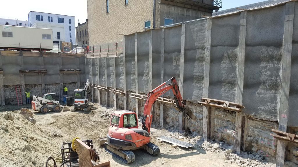
On the east and west sides of the site are located vintage brick buildings, both constructed in 1886, with three levels above grade and a full basement. The Foster House building is on the east of the project site and the Chicago House Hotel is on the west. Both structures are built tight to the lot lines with the Foster House extending approximately 9 inches over the property line and into the site. Figure 1 shows an overview of the site during excavation.
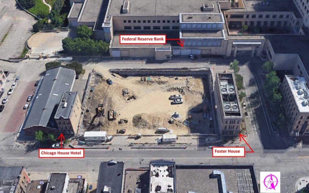
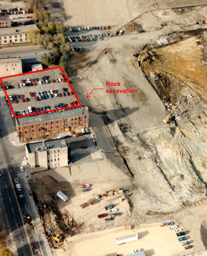
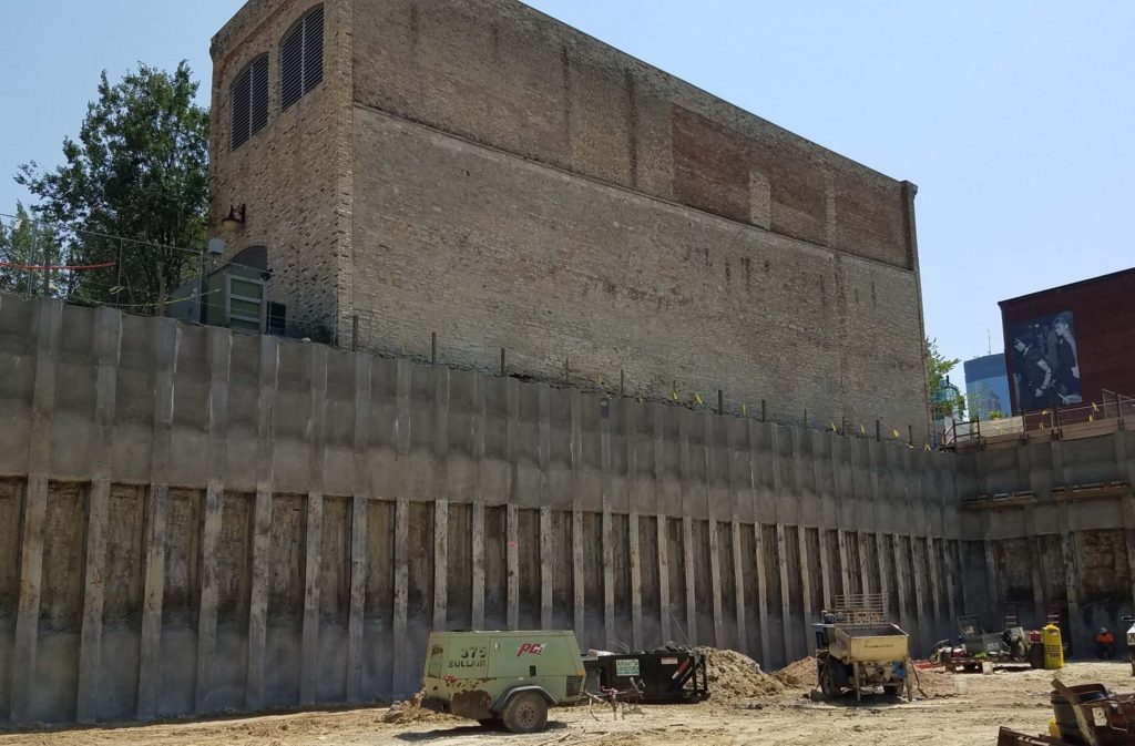
The large railroad yard was replaced by the Federal Reserve Bank Facility in 1997. Construction of the Federal Reserve included a large open excavation extending to an elevation approximately equal to the lowest parking level of The Archive. This excavation cut the bedrock at the north side of the site at an approximate 45° angle extending away from The Archive. Figure 2 shows the extent of that excavation, with The Archive site location denoted by the red outline. During this construction, the Foster House was converted to serve as a mechanical building supporting the Federal Reserve Bank.
Geotechnical Conditions
The general soil profile consists of 10 to 13 feet of urban fill comprised of silty sand, poorly graded sand, sandy lean clay, and miscellaneous debris over bedrock. The bedrock stratigraphy consists of a layer of Platteville Limestone varying between 8 to 12 feet thick over a 2 to 4-foot-thick layer of Glenwood Shale, sitting on St. Peter Sandstone. The Platteville Limestone has RQD values from 0 to 90 with an average of 37 and the Glenwood Shale is known to deteriorate if exposed for an extended time period.
Design
With parking at a premium in this area of downtown, and some nearby competing residential buildings touting approximately ½ of a parking space for every unit, The Archive desired to stand out, by maximizing the available parking for tenants. Incorporating three below grade levels, places the lowest floor a few feet above the water table, thus maximizing the depth of excavation.
Using traditional temporary retention and cast-in-place below-grade walls would have reduced the footprint of the building enough to remove one row of parking for all three levels. Therefore, the project team decided the temporary support of excavation (SOE) system would become the permanent below-grade wall to provide as much space as possible. The depth to bedrock prevented the use of sheet piles as the permanent foundation system and the limitations on the use of permanent tiebacks beyond the property line prevented the use of a soil nail system. A drilled system would be required, systems such as drilled soldier piles, secant walls, and diaphragm walls were explored. A drilled soldier pile system was proposed based on the cost and ability to meet project timelines.
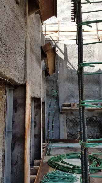
One of the hurdles to overcome with the drilled soldier pile system is the appearance of the permanent exposed facing. For The Archive, the upper portion of the wall supporting soil would have exposed shotcrete applied to the lagging. The stable bedrock would be left exposed and covered with rock netting. The elevations of the shale and sandstone would have shotcrete applied over the rock face.
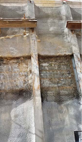
The shotcrete levels were reinforced with epoxy coated rebar and headed studs were welded to the webs of the piles to transfer the load. The shotcrete was placed at the back flange of the piles and the rock was excavated to the back flange of the piles. This was done to allow air flow to pass between the lower floors in the web of the piles, reducing the demand on the mechanical systems. Figure 3 shows a close up of the exposed face.
“The Federal Reserve Bank would not allow tiebacks to cross the property line, limiting the tieback length on the north wall to only an 18-foot horizontal dimension.”
By excavating as deep as practical and incorporating the temporary shoring into the permanent system, The Archive is able to create 1.5 parking spaces per unit. Some of these spaces will be used as public parking to generate revenue.
The design of the soldier piles had to consider both the temporary condition during construction and the permanent condition when it becomes part of the permanent structure. For the temporary SOE, the soldier piles used temporary tiebacks for lateral support. The design called for the tiebacks to remain in-place until the floor diaphragms were cast and grouted to the piles, whereby the floor diaphragms provide lateral support for the piles.
The Federal Reserve Bank would not allow tiebacks to cross the property line, limiting the tieback length on the north wall to only an 18-foot horizontal dimension. To achieve resistance in such a short horizontal length, the tiebacks would have to be bonded into the bedrock within the theoretical failure plane. Knowing the quality of the bedrock gave us confidence we would be able to provide adequate support in this condition. However, as shown by historical photos (Figure 2.), extensive rock excavation had occurred north of the site. Thus, there was a risk the bonded length of the tie-backs could extend into soils, rather than bedrock. To account for this, the tiebacks were installed at the lowest elevation the piles could support in a cantilevered condition and drilled in at a 45° angle to run parallel with the previously excavated rock surface.
On the east side, tiebacks were not allowed to be installed under the Foster House. While this building has a basement with strip footings bearing directly on the limestone bedrock, the planned excavations would remove the soil pressure on one side of the building, producing an unbalanced soil load that needed to be resisted by the shoring. The Foster House building only extends about two thirds of the site along this wall and the remainder of the wall had direct soil loading applied to the shoring.
Constructing a 31-foot-deep excavation without using tiebacks was going to be difficult. Options such as secant walls and internal braces were explored and determined to be to cost prohibitive and obstructive. The final design became a combination of drilled soldier piles, in-situ soil mixing, and post tensioning.
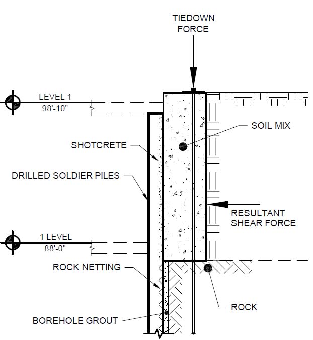
The Architect was able to provide three feet of space between the Foster House and the back of the soldier piles. The overburden soils in this space were soil mixed to the bedrock elevation, producing a 2,000 psi soil-cement matrix. Hollowbar tiedowns were installed off-center of the soil mix towards the Foster House and tensioned to provide overturning resistance. Because of the narrow distance, the tensioning of the tiebacks applied approximately 17 ksf of bearing pressure to the rock surface. The soldier piles were then designed as 20-foot tall cantilever elements resisting the shear force of the overburden soils only (not moment) and some notional lateral pressures from the bedrock. Figure 4 shows a schematic of the wall system, Figure 5 shows the soil mixing and Figure 6 shows the completed wall.
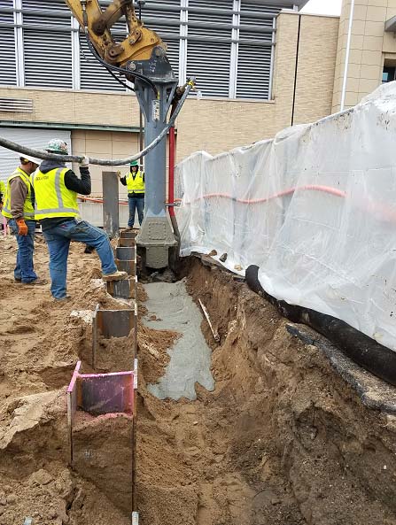
Since the piles were drilled and grouted with lean mix prior to the soil mix and tensioning, it was expected that the lean mix would fill in some of the existing fractures in the rock and provide an alternate load path, through bearing and side resistance, for the piles to help counterbalance the tensioning force.
Deflections of the wall were monitored and contingencies were planned if deflection limits were met – such as extensive corner bracing. The wall performed excellently, and deflections remained less than the notification limit of 1 inch at the top of the piles which translates to less than ½ inch at the existing building foundation level.
Tiebacks were allowed under the Chicago House Hotel on the west side of the site, simplifying the design considerably. Temporary tiebacks were placed immediately below the footing elevation, requiring the soldier piles to cantilever approximately 14 feet above the tiebacks. Figure 7 shows the excavation at the Chicago House Hotel, showing chipping of the rock between the piles.
Construction
The Archive was a design build project and excavation began as the structural and architectural designs were in process. The lower floors were designed as post tensioned slabs with columns close to the perimeter and the slabs cantilevering to the soldier pile wall. As a result, the solder pile wall was not required to carry substantial axial loads with the exception of three piles that did support columns loads.
Coordination was required to place the temporary tiebacks at elevations that did not interfere with the floor slabs, columns, or formwork for casting the floor slabs. With the tiebacks installed based on progress plans, a conflict was discovered in the field along the south wall where there were interferences with some columns and the temporary tiebacks. The entire team helped with the solution, the structural engineer was able to move some of the columns that were not yet cast. Temporary corner bracing was installed to remove some of the conflicts, such as shown in Figure 8. The remaining conflicts were solved by changing the forming system for the columns and shortening the bearing ends of the wales.
Conclusion
The Archive used an innovate application of drilled soldier piles as the permanent foundation wall and post tensioned soil mixing to maximize the structure footprint, while saving cost over a conventional wall system.
Project Team
Developer: Solhem Companies and TE Miller Development
Architect: Momentum Design Group
Structural Engineer: Ericksen Roed & Associates
General Contractor: Ironmark Building Company
Drilling and Shoring Contractor: Bolander
Geotechnical Engineer: Braun Intertec Corporation
Shoring Engineer: Braun Intertec Corporation